Personal project with Hugo Stynes
Timber reading lamp
I designed and built a reading lamp with a timber structure, warm LED lighting and rotary dimming. The work combined timber construction, embedded electronics and a physical control. I owned the electronics whilst Hugo Stynes owned the physical integration and timber construction.
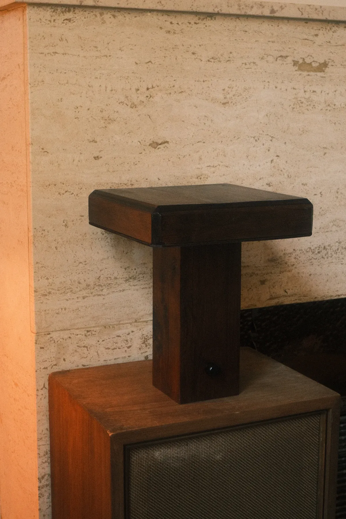
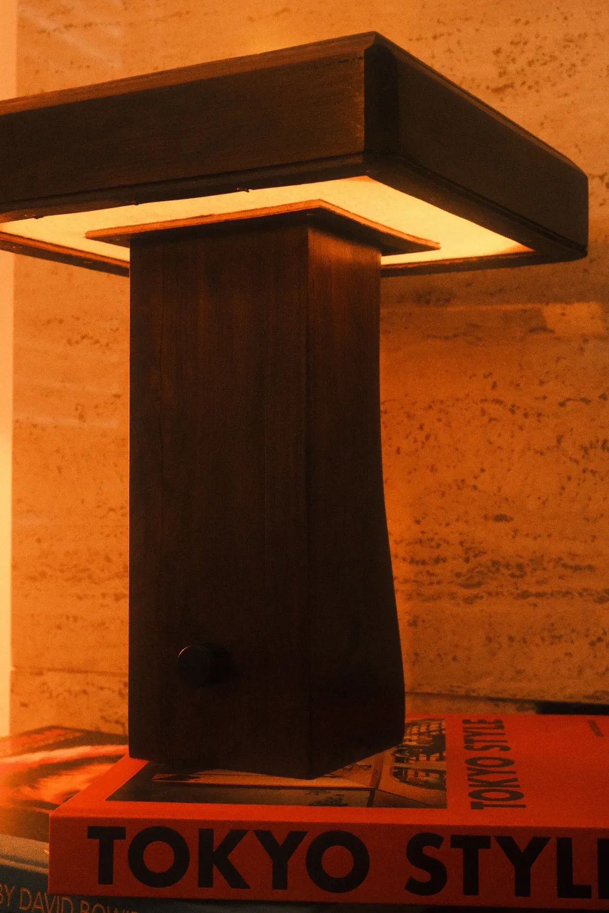
Form and construction
The lamp has a square timber head above a vertical base, with the dimming control on the front. The head houses the lighting, while the base accommodates the controller and wiring.
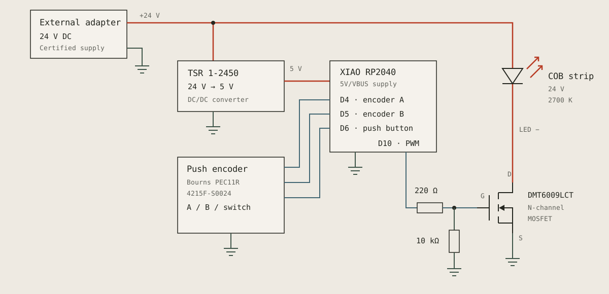
A physical dimming control
Turning the rotary control adjusts the LED brightness. The control sits on the front of the base, bringing the interaction into the lamp itself.
We used an exponential mapping to determine the duty cycle of MOSFET control. Gamma describes the exponent in a power-law mapping:
Here, input and output are normalised between 0 and 1. A gamma of 1 gives a straight-line relationship. A gamma greater than 1 makes the output rise slowly at first, then more quickly toward the top of the range.
The lamp uses γ = 2, so the firmware squares the brightness setting before converting it to PWM duty cycle. A halfway setting therefore produces roughly a quarter of the maximum duty cycle.
The point is to make dimming feel more even. Our perception of brightness is nonlinear, so equal steps in PWM duty cycle do not necessarily look like equal steps in brightness. This curve gives smaller duty-cycle changes near the dim end and larger changes near the bright end. Gamma 2 is a practical approximation, rather than a precise calibration of perceived brightness.
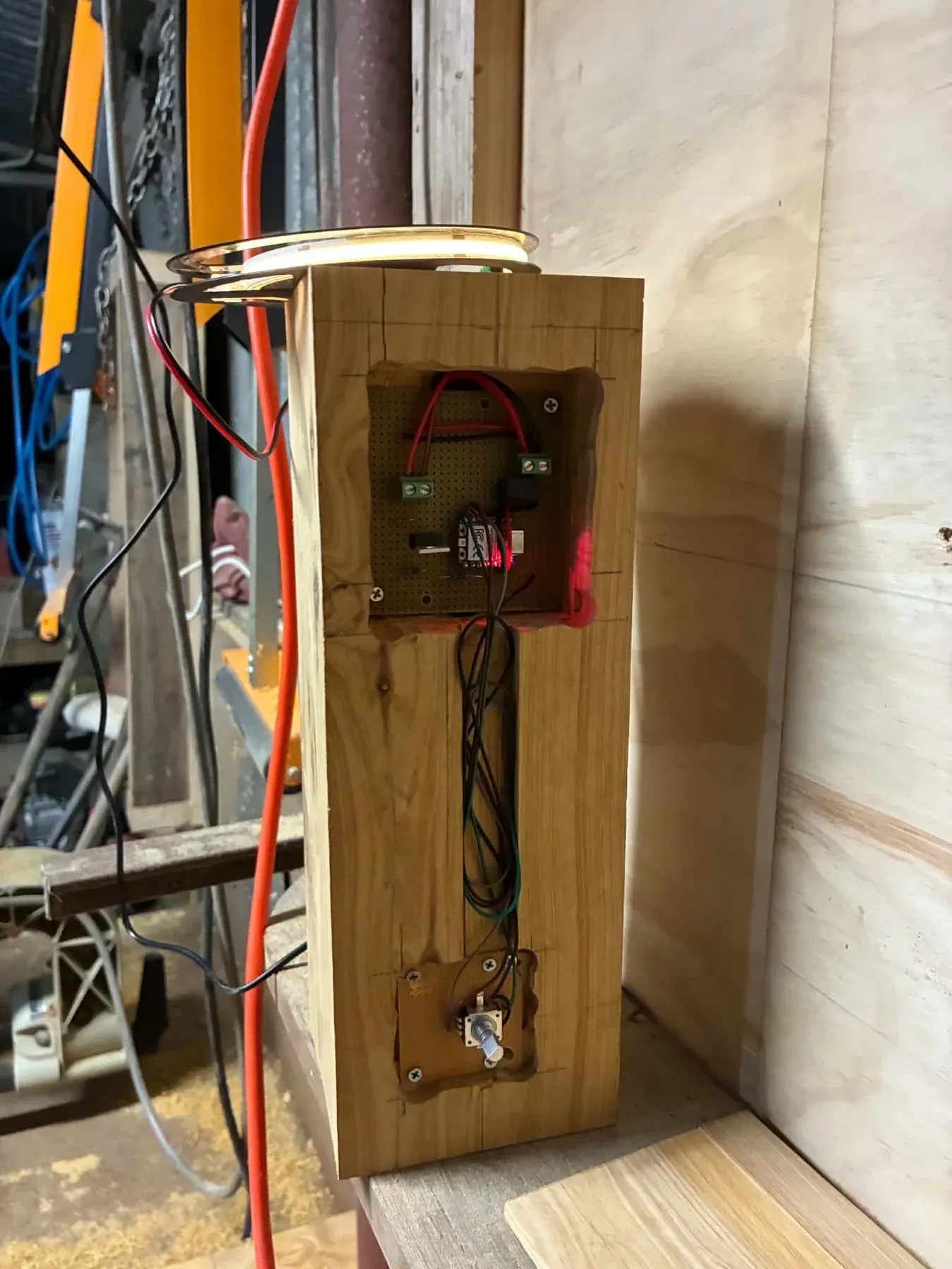
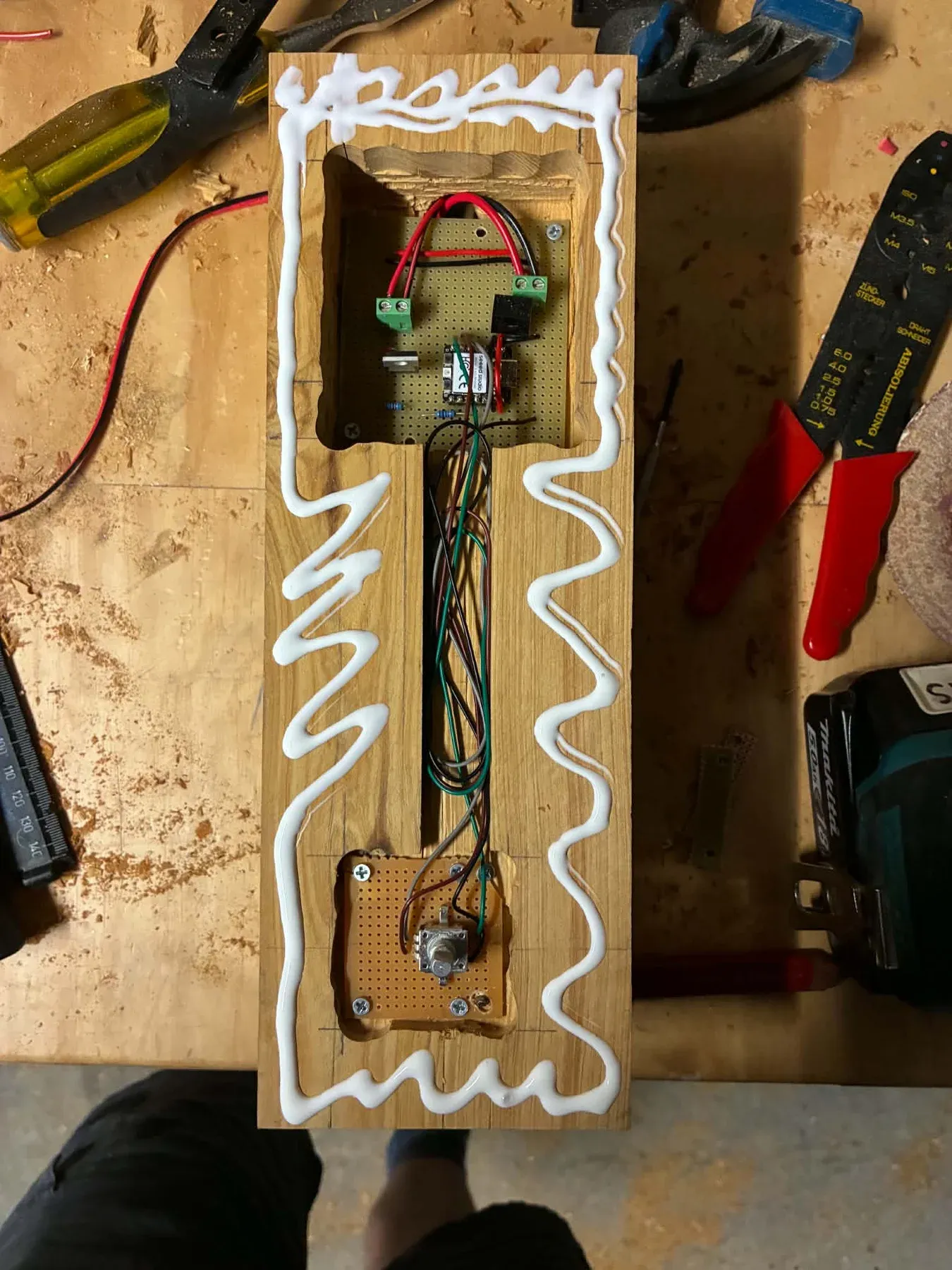
Embedded electronics connect the control to the lighting. The controller is installed inside the lamp, with the wiring contained within the timber enclosure.
Integrating the electronics
The internal assembly brings the controller, connections and wiring into a routed cavity in the timber. The open assembly photographs show how these parts fit within the finished form.
This version is a working prototype. The next revision will address how the electronics and enclosure can be assembled consistently across several lamps.
Testing the working lamp
The assembled lamp operates with rotary dimming, push-button on/off and the controller installed. On the working Veroboard circuit, I measured 23.435 V at the supply input and 5.006 V at the regulator output supplying the XIAO RP2040.
The MOSFET’s gate-to-source voltage was 0 V when switched off, and its drain-to-source voltage was approximately 0 V at maximum brightness. The COB strip went completely dark when commanded off.
I also recorded approximately 5.9 V across the MOSFET in the OFF state. The cause of this reading was not established, and no off-state current measurement was recorded.
I left the lamp running for 30 minutes and noticed no excess heat. This was a qualitative observation: temperature, ambient conditions and the brightness setting were not recorded. Longer-duration testing and temperature measurements would give a clearer picture of its thermal behaviour.
Tracking down a faint glow
The breadboard circuit initially worked, but after transport and a change from the bench supply to the wall adapter, the LED strip glowed faintly when commanded off.
I measured approximately 3 mV between the MOSFET’s gate and source, indicating that the gate was effectively at source potential. There was still approximately 19 V across the COB strip and 3.8 V across the MOSFET. Disconnecting the microcontroller’s gate drive while retaining the pulldown resistor did not eliminate the behaviour. Replacing the MOSFET also failed to resolve it.
The exact cause remained unresolved on the breadboard. The soldered version then supported rotary dimming, push-button control and a completely dark OFF state. That confirmed the working implementation. Although it did not establish the cause of the earlier breadboard glow, I suspect that it was a loose connection within the breadboard.
Designing for a small production run
For the second version, I plan to replace the prototype electronics with a custom PCB and a simpler, cheaper processor. The aim is to make the electronics repeatable and reduce the work involved in assembling each lamp.
The physical design also needs to be repeatable. We are considering how to manufacture it consistently in timber, or whether another material would be more suitable for a small pilot run. These changes are planned; the current lamp remains the working first version.